


/*********************************************************************
Various Maple tests.. including timer capture to memory via dma =)
включая захват таймера в память через dma
*/
#include "usb.h"
#include "timer.h"
#include "dma.h"
int PRESCALE=1 ; //32 ; //128;
int WAIT=1 ; //50;
int g=0 ;
int k=0 ;
int j=0 ;
int TRIGGER=26 ;
int BEAM=25 ;
int PULSE=27 ;
float RANGE=9 ; // range us
//quick method to return if there's anyone on the other end of the serialusb link yet.
boolean isConnected(){
return (SerialUSB.isConnected() && (SerialUSB.getDTR() || SerialUSB.getRTS()));
}
void setup(){
SerialUSB.begin();
while(!isConnected()); //wait till console attaches.
SerialUSB.println("Hello!");
SerialUSB.print(" Prescale: ");
SerialUSB.println(PRESCALE);
pinMode(27,INPUT_PULLDOWN);
//pinMode(26, INPUT_PULLUP);
pinMode(TRIGGER, INPUT_PULLDOWN);
pinMode(BEAM, INPUT);
}
/**********************************************************************
timer tests.. seeing if the timer clock really does run at 72mhz..
*/
volatile int overflowCount=0;
void countOverflows(){
overflowCount++;
}
//int PRESCALE=8 ; //32 ; //128;
//int WAIT=50;
int results[16];
int overflow[16];
void testHardwareTimer(HardwareTimer t){
t.attachInterrupt(1,countOverflows);
for(int i=0; i<16; i++){
t.setCount(0);
overflowCount=0;
t.resume();
delayMicroseconds(WAIT); // delay(WAIT);
t.pause();
results[i]=t.getCount();
overflow[i]=overflowCount;
}
t.detachInterrupt(1);
}
void printResults(){
SerialUSB.print("Timing results: ");
for(int i=0; i<16; i++){
SerialUSB.print(results[i]);
SerialUSB.print(" ");
}
SerialUSB.println();
SerialUSB.print("Overflows: ");
for(int i=0; i<16; i++){
SerialUSB.print(overflow[i]);
SerialUSB.print(" ");
}
SerialUSB.println();
SerialUSB.print("Each count worth approx (ns): ");
for(int i=0; i<16; i++){
SerialUSB.print( waitToNanos(overflow[i], results[i]) );
SerialUSB.print(" ");
}
SerialUSB.println();
}
double expectedTimePeriod(){
//in nanos.. so 72mhz = 72000khz = 72000000hz 1/72000000hz = tick in seconds
// 1/72000 = tick in ms, 1/72 = tick in us (1/72) * 1000 = tick in ns
//tick in ns * prescale == time которое мы должны видеть
//we're supposed to see
return ((double)1.0 / ((double)72.0)) * (double)1000.0 * (double)PRESCALE;
}
double waitToNanos( int overflows, int count ){
//wait is in millis, *1000 for micros, *1000 for nanos
double time = (((double)WAIT * (double)1000.0)) ; // * (double)1000.0) ) ;
time = time / ((double)count + ((double)65535*(double)overflows));
return time;
}
int readInt(char terminator){
char current;
int output=0;
while(SerialUSB.available() && (current=SerialUSB.read())!=terminator){
if(current>='0' && current<='9'){
output=output*10;
output+=(current-'0');
}else{
output=-1;
break;
}
}
return output;
}
HardwareTimer timer2 = HardwareTimer(2);
HardwareTimer timer1 = HardwareTimer(1);
void timingTest(){
SerialUSB.println("Starting Timing test");
SerialUSB.print(" Prescale: ");
SerialUSB.println(PRESCALE);
SerialUSB.print(" Wait Period (us): ");
SerialUSB.println(WAIT);
SerialUSB.print(" Expected value for each tick :");
SerialUSB.println(expectedTimePeriod());
timer1.pause();
timer2.pause();
timer2.setMode(TIMER_CH1, TIMER_OUTPUT_COMPARE);
timer2.setPrescaleFactor(PRESCALE);
timer2.setOverflow(65535);
timer2.setCompare(1,65535);
timer2.setCount(0);
timer2.refresh();
timer1.setMode(TIMER_CH1, TIMER_OUTPUT_COMPARE);
timer1.setPrescaleFactor(PRESCALE);
timer1.setOverflow(65535);
timer1.setCompare(1,65535);
timer1.setCount(0);
timer1.refresh();
testHardwareTimer(timer1);
printResults();
testHardwareTimer(timer2);
printResults();
}
/******************************************************************************
DMA from Timer Capture to array test..
*/
//number of captures to do..
#define TIMERS 100 //512
volatile int exit=0; //set to 1 when dma complete.
volatile uint16 data[TIMERS]; //place to put the data via dma
//dump routine to show content of captured data.
void printData(){
SerialUSB.print("DATA: ");
for(int i=0; i<TIMERS; i++){
SerialUSB.print(data[i]);
SerialUSB.print(" ");
}
SerialUSB.println();
}
//активизировать (invoked) as configured by the DMA mode flags.
void dma_isr()
{
dma_irq_cause cause = dma_get_irq_cause(DMA1, DMA_CH2);
//using serialusb to print messages here is nice, but
//it takes so long, we may never exit this isr invocation
//before the next one comes in.. (dma is fast.. m'kay)
switch(cause)
{
case DMA_TRANSFER_COMPLETE:
// Transfer completed
SerialUSB.println("DMA Complete");
exit=1;
break;
case DMA_TRANSFER_HALF_COMPLETE:
// Transfer is half complete
SerialUSB.println("DMA Half Complete");
break;
case DMA_TRANSFER_ERROR:
// An error occurred during transfer
SerialUSB.println("DMA Error");
exit=1;
break;
default:
// Something went horribly wrong.
// Should never happen.
SerialUSB.println("DMA WTF");
exit=1;
break;
}
}
void loop(){
//simple main loop, listens for a char, and uses it as a command
//to select what task to perform
//
// a echo test
// b echo test
// c serialusb disable/enable test
// d time the timer test, default params
// e time the timer test, user supplied args
// f DMA timer capture of pulse widths from D6 straight to memory
while(!SerialUSB.available());
char cmd = SerialUSB.read();
switch(cmd)
{
case 'a':
{
SerialUSB.println("Hello");
break;
}
case 'b':
{
SerialUSB.println("There");
break;
}
case 'c':
{
SerialUSB.println("Going away for a while");
SerialUSB.end();
usbPowerOff();
delay(5000);
usbPowerOn();
SerialUSB.begin();
delay(5000);
while(!isConnected());
SerialUSB.println("Welcome back");
break;
}
case 'd':
{
// WAIT=50;
// PRESCALE=128;
timingTest(); printData();
break;
}
case 'p':
{
printData();
break;
}
case 'i':
{
// attachInterrupt(26, blink, RISING);
attachInterrupt(TRIGGER, TRIGGER_ON, FALLING);
// printData();
break;
}
case 'e':
{
int arg1=0;
int arg2=0;
if(!SerialUSB.available())
goto usage;
if(SerialUSB.read()!=' ')
goto usage;
arg1 = readInt(' ');
arg2 = readInt(' ');
if(arg1==-1 || arg2==-1)
goto usage;
SerialUSB.print("Setting prescale to: ");
SerialUSB.println(arg1);
SerialUSB.print("Setting wait to: ");
SerialUSB.println(arg2);
WAIT=arg2;
PRESCALE=arg1;
timingTest();
goto done;
usage:
SerialUSB.println("Usage: e <prescale> <wait>");
SerialUSB.println(" eg. e 128 200 for a prescale of 128 and wait of 200");
done:
break;
}
case 'f':{
timer_dev *t = TIMER1;
timer1.pause();
timer1.setPrescaleFactor(PRESCALE) ; //128);
timer1.setOverflow(65535);
timer1.setCount(0);
timer1.refresh();
timer_reg_map r = t->regs;
//using timer1, channel1, maps to pin d27
//according to maple master pin map.
// pinMode(27,INPUT_PULLUP);
//capture compare regs TIMx_CCRx used to hold val after a transition on corresponding ICx
//when cap occurs, flag CCXIF (TIMx_SR register) is set,
//and interrupt, or dma req can be sent if they are enabled.
//if cap occurs while flag is already high CCxOF (overcapture) flag is set..
//CCIX can be cleared by writing 0, or by reading the capped data from TIMx_CCRx
//CCxOF is cleared by writing 0 to it.
//Capture/Compare 1 Selection
// set CC1S bits to 01 in the capture compare mode register.
// 01 selects TI1 as the input to use. (page 336 stm32 reference)
// (assuming here that TI1 is D6, according to maple master pin map)
//CC1S bits are bits 0,1
bitSet(r.adv->CCMR1, 0);
bitClear(r.adv->CCMR1, 1);
//Input Capture 1 Filter.
// need to set IC1F bits according to a table saying how long
// we should wait for a signal to be 'stable' to validate a transition
// on the input.
// (page 336 stm32 reference)
//IC1F bits are bits 7,6,5,4
bitClear(r.adv->CCMR1, 7);
bitClear(r.adv->CCMR1, 6);
bitSet(r.adv->CCMR1, 5);
bitSet(r.adv->CCMR1, 4);
//sort out the input capture prescaler..
//00 no prescaler.. capture is done as soon as edge is detected
bitClear(r.adv->CCMR1, 3);
bitClear(r.adv->CCMR1, 2);
//select the edge for the transition on TI1 channel using CC1P in CCER
//CC1P is bit 1 of CCER (page 339)
// 0 = falling
// 1 = rising
bitClear(r.adv->CCER,1);
//set the CC1E bit to enable capture from the counter.
//CCE1 is bit 0 of CCER (page 339)
bitSet(r.adv->CCER,0);
//enable dma for this timer..
//sets the Capture/Compare 1 DMA request enable bit on the DMA/interrupt enable register.
//bit 9 is CC1DE as defined on page 329.
bitSet(r.adv->DIER,9);
dma_init(DMA1);
dma_setup_transfer( DMA1, //dma device, dma1 here because that's the only one we have
DMA_CH2, //dma channel, channel2, because it looks after tim1_ch1 (timer1, channel1)
&(r.adv->CCR1), //peripheral address
DMA_SIZE_16BITS, //peripheral size
data, //memory address
DMA_SIZE_16BITS, //memory transfer size
(0
//| DMA_FROM_MEM //set if going from memory, don't set if going to memory.
| DMA_MINC_MODE //auto inc where the data does in memory (uses size_16bits to know how much)
| DMA_TRNS_ERR //tell me if it's fubar
//| DMA_HALF_TRNS //tell me half way (actually, don't as I spend so long there, I dont see 'complete')
| DMA_TRNS_CMPLT //tell me at the end
)
);
fff() ;
printData();
break;
}
case 's':{
pinMode(27,INPUT_PULLUP);
for(g=0 ;g<4 ;g++){
timer_dev *t = TIMER1;
timer1.pause();
timer1.setPrescaleFactor(PRESCALE) ; //128);
timer1.setOverflow(65535);
timer1.setCount(0);
timer1.refresh();
timer_reg_map r = t->regs;
//using timer1, channel1, maps to pin d27
//according to maple master pin map.
//capture compare regs TIMx_CCRx used to hold val after a transition on corresponding ICx
//when cap occurs, flag CCXIF (TIMx_SR register) is set,
//and interrupt, or dma req can be sent if they are enabled.
//if cap occurs while flag is already high CCxOF (overcapture) flag is set..
//CCIX can be cleared by writing 0, or by reading the capped data from TIMx_CCRx
//CCxOF is cleared by writing 0 to it.
//Capture/Compare 1 Selection
// set CC1S bits to 01 in the capture compare mode register.
// 01 selects TI1 as the input to use. (page 336 stm32 reference)
// (assuming here that TI1 is D6, according to maple master pin map)
//CC1S bits are bits 0,1
bitSet(r.adv->CCMR1, 0);
bitClear(r.adv->CCMR1, 1);
//Input Capture 1 Filter.
// need to set IC1F bits according to a table saying how long
// we should wait for a signal to be 'stable' to validate a transition
// on the input.
// (page 336 stm32 reference)
//IC1F bits are bits 7,6,5,4
bitClear(r.adv->CCMR1, 7);
bitClear(r.adv->CCMR1, 6);
bitSet(r.adv->CCMR1, 5);
bitSet(r.adv->CCMR1, 4);
//sort out the input capture prescaler..
//00 no prescaler.. capture is done as soon as edge is detected
bitClear(r.adv->CCMR1, 3);
bitClear(r.adv->CCMR1, 2);
//select the edge for the transition on TI1 channel using CC1P in CCER
//CC1P is bit 1 of CCER (page 339)
// 0 = falling
// 1 = rising
bitClear(r.adv->CCER,1);
//set the CC1E bit to enable capture from the counter.
//CCE1 is bit 0 of CCER (page 339)
bitSet(r.adv->CCER,0);
//enable dma for this timer..
//sets the Capture/Compare 1 DMA request enable bit on the DMA/interrupt enable register.
//bit 9 is CC1DE as defined on page 329.
bitSet(r.adv->DIER,9);
dma_init(DMA1);
dma_setup_transfer( DMA1, //dma device, dma1 here because that's the only one we have
DMA_CH2, //dma channel, channel2, because it looks after tim1_ch1 (timer1, channel1)
&(r.adv->CCR1), //peripheral address
DMA_SIZE_16BITS, //peripheral size
data, //memory address
DMA_SIZE_16BITS, //memory transfer size
(0
//| DMA_FROM_MEM //set if going from memory, don't set if going to memory.
| DMA_MINC_MODE //auto inc where the data does in memory (uses size_16bits to know how much)
| DMA_TRNS_ERR //tell me if it's fubar
//| DMA_HALF_TRNS //tell me half way (actually, don't as I spend so long there, I dont see 'complete')
| DMA_TRNS_CMPLT //tell me at the end
)
);
fff() ;
} //for
printData();
break;
}
}
}
void fff() {
dma_attach_interrupt(DMA1, DMA_CH2, dma_isr); //hook up an isr for the dma chan to tell us if things happen.
dma_set_num_transfers(DMA1, DMA_CH2, TIMERS); //only allow it to transfer TIMERS number of times.
dma_enable(DMA1, DMA_CH2); //enable it..
timer1.resume();
// while(!exit);
delayMicroseconds(RANGE) ;
// exit=1;
// detachInterrupt(PULSE) ;
// timer1.pause();
dma_disable(DMA1, DMA_CH2);
dma_detach_interrupt(DMA1, DMA_CH2);
// printData();
detachInterrupt(BEAM) ;
printData();
j=j+1 ;
SerialUSB.print("j=");SerialUSB.println(j);
////////////////////////////////////
DMA_RET () ;
attachInterrupt(BEAM, BEAM_ON , RISING);
}
//void blink(){
// attachInterrupt(PULSE, ....., FALLING);
//detachInterrupt(BEAM) ;
// delay(2) ;
// fff() ;
//}
void TRIGGER_ON(){
DMA_FT () ;
attachInterrupt(BEAM, fff , RISING);
// detachInterrupt(TRIGGER) ;
// attachInterrupt(TRIGGER, NEXT_ROT, FALLING);
k=k+1 ;
j=0 ;
// delay(2) ;
}
void BEAM_ON(){
// j=j+1 ;
fff () ;
// dma_disable(DMA1, DMA_CH2);
// dma_detach_interrupt(DMA1, DMA_CH2);
// attachInterrupt(PULSE, fff , RISING);
// attachInterrupt(PULSE, ....., FALLING);
// detachInterrupt(PULSE) ;
// delay(2) ;
// blink() ;
}
/*
void NEXT_ROT(){
j=j+1 ;
attachInterrupt(PULSE, blink, RISING);
// attachInterrupt(PULSE, ....., FALLING);
// detachInterrupt(PULSE) ;
// delay(2) ;
blink() ;
}
*/
void DMA_RET()
{
// pinMode(27,INPUT_PULLUP);
timer_dev *t = TIMER1;
timer1.pause();
// timer1.setPrescaleFactor(PRESCALE) ; //128);
// timer1.setOverflow(65535);
timer1.setCount(0);
timer1.refresh();
timer_reg_map r = t->regs;
/*
//using timer1, channel1, maps to pin d27
//according to maple master pin map.
// pinMode(27,INPUT_PULLUP);
//capture compare regs TIMx_CCRx used to hold val after a transition on corresponding ICx
//when cap occurs, flag CCXIF (TIMx_SR register) is set,
//and interrupt, or dma req can be sent if they are enabled.
//if cap occurs while flag is already high CCxOF (overcapture) flag is set..
//CCIX can be cleared by writing 0, or by reading the capped data from TIMx_CCRx
//CCxOF is cleared by writing 0 to it.
//Capture/Compare 1 Selection
// set CC1S bits to 01 in the capture compare mode register.
// 01 selects TI1 as the input to use. (page 336 stm32 reference)
// (assuming here that TI1 is D6, according to maple master pin map)
//CC1S bits are bits 0,1
bitSet(r.adv->CCMR1, 0);
bitClear(r.adv->CCMR1, 1);
//Input Capture 1 Filter.
// need to set IC1F bits according to a table saying how long
// we should wait for a signal to be 'stable' to validate a transition
// on the input.
// (page 336 stm32 reference)
//IC1F bits are bits 7,6,5,4
bitClear(r.adv->CCMR1, 7);
bitClear(r.adv->CCMR1, 6);
bitSet(r.adv->CCMR1, 5);
bitSet(r.adv->CCMR1, 4);
//sort out the input capture prescaler..
//00 no prescaler.. capture is done as soon as edge is detected
bitClear(r.adv->CCMR1, 3);
bitClear(r.adv->CCMR1, 2);
//select the edge for the transition on TI1 channel using CC1P in CCER
//CC1P is bit 1 of CCER (page 339)
// 0 = falling
// 1 = rising
bitClear(r.adv->CCER,1);
//set the CC1E bit to enable capture from the counter.
//CCE1 is bit 0 of CCER (page 339)
bitSet(r.adv->CCER,0);
//enable dma for this timer..
//sets the Capture/Compare 1 DMA request enable bit on the DMA/interrupt enable register.
//bit 9 is CC1DE as defined on page 329.
bitSet(r.adv->DIER,9);
*/
// dma_init(DMA1);
dma_setup_transfer( DMA1, //dma device, dma1 here because that's the only one we have
DMA_CH2, //dma channel, channel2, because it looks after tim1_ch1 (timer1, channel1)
&(r.adv->CCR1), //peripheral address
DMA_SIZE_16BITS, //peripheral size
data, //memory address
DMA_SIZE_16BITS, //memory transfer size
(0
//| DMA_FROM_MEM //set if going from memory, don't set if going to memory.
// | DMA_MINC_MODE //auto inc where the data does in memory (uses size_16bits to know how much)
// | DMA_TRNS_ERR //tell me if it's fubar
//| DMA_HALF_TRNS //tell me half way (actually, don't as I spend so long there, I dont see 'complete')
// | DMA_TRNS_CMPLT //tell me at the end
)
);
// fff() ;
// printData();
}
void DMA_FT()
{
timer_dev *t = TIMER1;
timer1.pause();
timer1.setPrescaleFactor(PRESCALE) ; //128);
timer1.setOverflow(65535);
timer1.setCount(0);
timer1.refresh();
timer_reg_map r = t->regs;
//using timer1, channel1, maps to pin d27
//according to maple master pin map.
// pinMode(27,INPUT_PULLUP);
//capture compare regs TIMx_CCRx used to hold val after a transition on corresponding ICx
//when cap occurs, flag CCXIF (TIMx_SR register) is set,
//and interrupt, or dma req can be sent if they are enabled.
//if cap occurs while flag is already high CCxOF (overcapture) flag is set..
//CCIX can be cleared by writing 0, or by reading the capped data from TIMx_CCRx
//CCxOF is cleared by writing 0 to it.
//Capture/Compare 1 Selection
// set CC1S bits to 01 in the capture compare mode register.
// 01 selects TI1 as the input to use. (page 336 stm32 reference)
// (assuming here that TI1 is D6, according to maple master pin map)
//CC1S bits are bits 0,1
bitSet(r.adv->CCMR1, 0);
bitClear(r.adv->CCMR1, 1);
//Input Capture 1 Filter.
// need to set IC1F bits according to a table saying how long
// we should wait for a signal to be 'stable' to validate a transition
// on the input.
// (page 336 stm32 reference)
//IC1F bits are bits 7,6,5,4
bitClear(r.adv->CCMR1, 7);
bitClear(r.adv->CCMR1, 6);
bitSet(r.adv->CCMR1, 5);
bitSet(r.adv->CCMR1, 4);
//sort out the input capture prescaler..
//00 no prescaler.. capture is done as soon as edge is detected
bitClear(r.adv->CCMR1, 3);
bitClear(r.adv->CCMR1, 2);
//select the edge for the transition on TI1 channel using CC1P in CCER
//CC1P is bit 1 of CCER (page 339)
// 0 = falling
// 1 = rising
bitClear(r.adv->CCER,1);
//set the CC1E bit to enable capture from the counter.
//CCE1 is bit 0 of CCER (page 339)
bitSet(r.adv->CCER,0);
//enable dma for this timer..
//sets the Capture/Compare 1 DMA request enable bit on the DMA/interrupt enable register.
//bit 9 is CC1DE as defined on page 329.
bitSet(r.adv->DIER,9);
dma_init(DMA1);
dma_setup_transfer( DMA1, //dma device, dma1 here because that's the only one we have
DMA_CH2, //dma channel, channel2, because it looks after tim1_ch1 (timer1, channel1)
&(r.adv->CCR1), //peripheral address
DMA_SIZE_16BITS, //peripheral size
data, //memory address
DMA_SIZE_16BITS, //memory transfer size
(0
//| DMA_FROM_MEM //set if going from memory, don't set if going to memory.
//| DMA_MINC_MODE //auto inc where the data does in memory (uses size_16bits to know how much)
//| DMA_TRNS_ERR //tell me if it's fubar
//| DMA_HALF_TRNS //tell me half way (actually, don't as I spend so long there, I dont see 'complete')
//| DMA_TRNS_CMPLT //tell me at the end
)
);
}
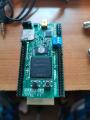
пример, мини мэпл, с мэпл компилятором.
Сообщение отредактировал nvc: 15 марта 2020 - 14:27
Добавил теги code